Bevel Gear Jacks BG250 (15 Ton)
BG250S, BG250D
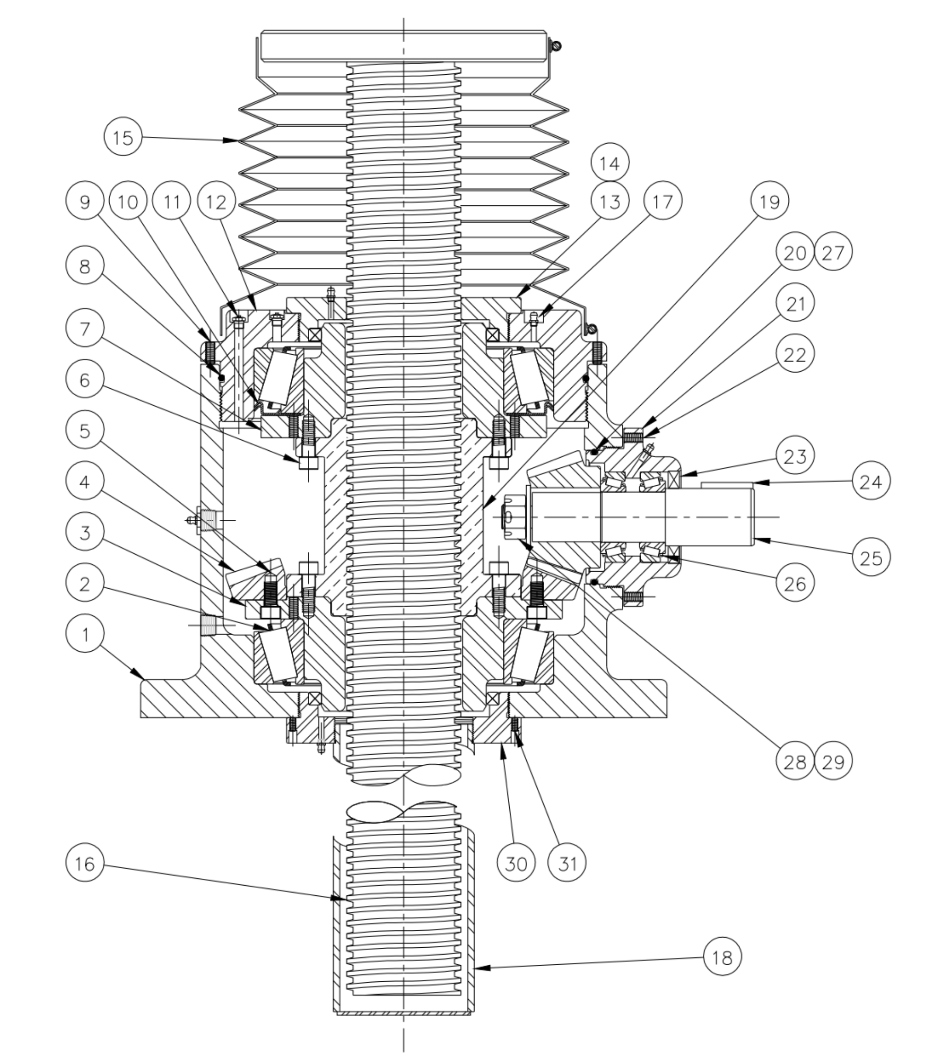
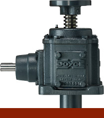
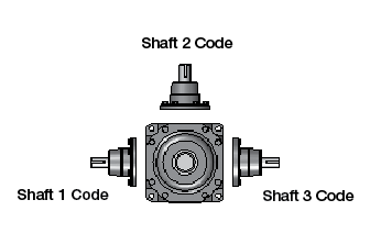
Joyce BG250S and BG250D bevel gear jacks with a 15-ton static capacity, offer higher efficiency and greater speed than other mechanical screw jacks. As an added benefit, these mechanical actuators also act as miter boxes, making them an ideal choice for multi-jack systems. As many as three output shafts may be specified for mounting motors, limit switches, readout devices and other accessories. BG250 jacks with single lead screws (S series) provide the benefits of a self-locking screw, and bevel gear jacks with double lead screws (D series) offer even greater travel speed.
- 2 ½" diameter lifting screw
- Choose one of four standard end conditions
- Protective boots and other options are available
- Right hand and left hand screw threads are available
- Joyce/Dayton can customize to your specifications
2D/3D Drawings
Login to access 2D/3D Drawings
Product Media

Available Models
- Ductile Iron housing
- Lifting screw, CDS
- Aluminum Bronze traveling nut (KFTN)
- Input shaft, CDS
Sample Part Number:
Click on the part number to reveal additional informaton about jack designs and shaft codes.
Model Number
| Joyce Bevel Gear® Jacks | |
|---|---|
| BG150S | BG1500S |
| BG250S | BG150S |
| BG375S | BG150S |
| BG450S | BG150S |
Jack Configuration
| Jack Configuration | ||
|---|---|---|
 |
 |
|
| U= Upright | I= Inverted | |
End Conditions

Jack Design
| Actuator Design | ||
|---|---|---|
 |
 |
 |
| S= Translating | Keyed for Non Rotation | N= Travelling Nut |
Bevel Ball Actuator Rise
| Bevel Ball Actuator Rise |
|---|
| Rise is travel expressed in inches and not the actual screw length |

| Shaft Codes |
|---|
| Three shaft codes must be specified for each jack. Electronic and mechanical limit switches may be substituted for the shaft code per the tables on this page. |
| STDX- Standard |
| XXXX- Input shaft no required |
| When ordering with only one input shaft, it is recommended to order the following configuration: XXXX-STDX-XXXX |
Additional Options X= Standard Jack, no additional options X= Additional Specification Required (comment as necessary) Protective Boots B= Protective Boot D= Dual Protective Boot Finishes F1= Do Not Paint F2= Epoxy Paint F3= Outdoor Paint processes ACME Screw L= Left hand Screw Screw Stops ST0=Extending
ST1=Retracting
ST2=Both
| Model | Dynamic Capacity | Upright Assembly: Screw-in compression/ inverted assembly: screw-in tension |
Upright Assembly: screw-in tension/ inverted assembly: Screw-in compression | Screw Dia. | Screw Pitch/Lead | Bevel Gear Ratio | Pinion Turns for 1" Travel | Pinion Torque (In. Lbs.) | Screw Torque | Jack Efficiency | Jack† Cooling Time | Base Weight (Lbs.) | Add for Each Inch of Travel (Lbs.) |
|---|---|---|---|---|---|---|---|---|---|---|---|---|---|
| BG250-S | Please use JAX Software or contact Joyce / Dayton |
30,000 lbs. | 30,000 lbs. | 2 ½" | .500 P ACME 2C | 2.15:1 | 4.31 | .111W* | .227W* | 34.2% | 82 min. | 140 | 2.6 |
| BG250-D* | 30,000 lbs. | 30,000 lbs. | 2 ½" | .375P / .750L ACME 2C | 2.15:1 | 2.87 | .133W* | .272W* | 42.6% | 82 min. | 140 | 2.6 |
Important Note: *Not self-locking, may lower under load. Brake motors or external locking systems are recommended.
D: Double Lead Screws.
S: Single Lead Screws. These jacks are self-locking.
*W: Load in Pounds.
Pinion Torque: The torque required to continuously raise a given load.
Screw Torque: The torque required to resist screw rotation (translating jack design) and traveling nut rotation (keyed for traveling nut design).
Lead: The distance traveled axially in one rotation of the lifting screw.
Pitch: The distance from a point on the screw thread to a corresponding point on the next thread, measured axially.
†: Cooling time based on time to cool from 200°F to 70°F (ambient).
